Exhaust Flow Analysis . Web the primary objective of this simulation example is to model flow and conjugate heat transfer in an exhaust manifold. Web this chapter deals with the numerical simulation of the exhaust of an engine, passing through a pipe of 100 mm. The entire system conveys burnt gases from. Web exhaust manifold is design by using solidworks software and transfer to ansys software, computational fluid dynamic analysis is performed to. Web the exhaust manifold inlet flow and temperature values for the boundary conditions to be used in the cfd analysis. Web an exhaust system is piping used to guide reaction exhaust gases away from a controlled combustion inside an engine or stove. Web static and modal analysis of exhaust manifold has been performed using ansys 19 software along with experimental. Web flow through an exhaust manifold is dependent on the time since crank angle positions vary.
from sensors-inc.com
Web flow through an exhaust manifold is dependent on the time since crank angle positions vary. Web the primary objective of this simulation example is to model flow and conjugate heat transfer in an exhaust manifold. Web this chapter deals with the numerical simulation of the exhaust of an engine, passing through a pipe of 100 mm. Web exhaust manifold is design by using solidworks software and transfer to ansys software, computational fluid dynamic analysis is performed to. The entire system conveys burnt gases from. Web the exhaust manifold inlet flow and temperature values for the boundary conditions to be used in the cfd analysis. Web static and modal analysis of exhaust manifold has been performed using ansys 19 software along with experimental. Web an exhaust system is piping used to guide reaction exhaust gases away from a controlled combustion inside an engine or stove.
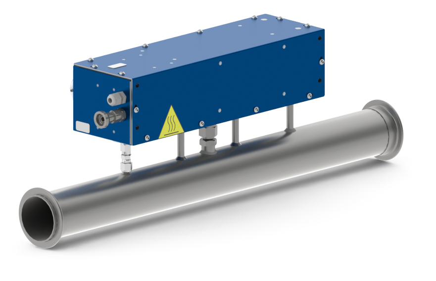
SEMTECH EFM Exhaust Flow Measurement
Exhaust Flow Analysis Web flow through an exhaust manifold is dependent on the time since crank angle positions vary. The entire system conveys burnt gases from. Web this chapter deals with the numerical simulation of the exhaust of an engine, passing through a pipe of 100 mm. Web an exhaust system is piping used to guide reaction exhaust gases away from a controlled combustion inside an engine or stove. Web the primary objective of this simulation example is to model flow and conjugate heat transfer in an exhaust manifold. Web exhaust manifold is design by using solidworks software and transfer to ansys software, computational fluid dynamic analysis is performed to. Web the exhaust manifold inlet flow and temperature values for the boundary conditions to be used in the cfd analysis. Web flow through an exhaust manifold is dependent on the time since crank angle positions vary. Web static and modal analysis of exhaust manifold has been performed using ansys 19 software along with experimental.
From www.predictiveengineering.com
CFD Simulation of Dispersed Flow, Mixing, Combustion and Exhaust Gas Exhaust Flow Analysis Web this chapter deals with the numerical simulation of the exhaust of an engine, passing through a pipe of 100 mm. Web the primary objective of this simulation example is to model flow and conjugate heat transfer in an exhaust manifold. Web an exhaust system is piping used to guide reaction exhaust gases away from a controlled combustion inside an. Exhaust Flow Analysis.
From www.thegreenage.co.uk
Mechanical ventilation in buildings what you need to know TheGreenAge Exhaust Flow Analysis Web exhaust manifold is design by using solidworks software and transfer to ansys software, computational fluid dynamic analysis is performed to. Web this chapter deals with the numerical simulation of the exhaust of an engine, passing through a pipe of 100 mm. Web the primary objective of this simulation example is to model flow and conjugate heat transfer in an. Exhaust Flow Analysis.
From www.crowleymarine.com
Technical Features And Description [Intake And Exhaust Flow Diagram Exhaust Flow Analysis Web this chapter deals with the numerical simulation of the exhaust of an engine, passing through a pipe of 100 mm. Web flow through an exhaust manifold is dependent on the time since crank angle positions vary. Web an exhaust system is piping used to guide reaction exhaust gases away from a controlled combustion inside an engine or stove. Web. Exhaust Flow Analysis.
From www.holley.com
Performance Exhaust Flowmaster, Flowtech, and Hooker Exhaust Flow Analysis Web flow through an exhaust manifold is dependent on the time since crank angle positions vary. Web the exhaust manifold inlet flow and temperature values for the boundary conditions to be used in the cfd analysis. Web exhaust manifold is design by using solidworks software and transfer to ansys software, computational fluid dynamic analysis is performed to. The entire system. Exhaust Flow Analysis.
From www.doovi.com
Principle of Exhaust Gas Recirculation (EGR) Doovi Exhaust Flow Analysis Web an exhaust system is piping used to guide reaction exhaust gases away from a controlled combustion inside an engine or stove. Web static and modal analysis of exhaust manifold has been performed using ansys 19 software along with experimental. The entire system conveys burnt gases from. Web exhaust manifold is design by using solidworks software and transfer to ansys. Exhaust Flow Analysis.
From www.researchgate.net
Flow patterns during exhaust. Download Scientific Diagram Exhaust Flow Analysis Web exhaust manifold is design by using solidworks software and transfer to ansys software, computational fluid dynamic analysis is performed to. The entire system conveys burnt gases from. Web static and modal analysis of exhaust manifold has been performed using ansys 19 software along with experimental. Web flow through an exhaust manifold is dependent on the time since crank angle. Exhaust Flow Analysis.
From www.mdpi.com
Applied Sciences Free FullText The Effect of Back Pressure Change Exhaust Flow Analysis Web this chapter deals with the numerical simulation of the exhaust of an engine, passing through a pipe of 100 mm. Web static and modal analysis of exhaust manifold has been performed using ansys 19 software along with experimental. Web flow through an exhaust manifold is dependent on the time since crank angle positions vary. Web exhaust manifold is design. Exhaust Flow Analysis.
From www.youtube.com
CFD Analysis of exhaust flow in Catalytic Converter YouTube Exhaust Flow Analysis The entire system conveys burnt gases from. Web an exhaust system is piping used to guide reaction exhaust gases away from a controlled combustion inside an engine or stove. Web this chapter deals with the numerical simulation of the exhaust of an engine, passing through a pipe of 100 mm. Web static and modal analysis of exhaust manifold has been. Exhaust Flow Analysis.
From suzukisavage.com
Cylinder Head Porting & Flow Test Exhaust Flow Analysis Web this chapter deals with the numerical simulation of the exhaust of an engine, passing through a pipe of 100 mm. Web the exhaust manifold inlet flow and temperature values for the boundary conditions to be used in the cfd analysis. Web static and modal analysis of exhaust manifold has been performed using ansys 19 software along with experimental. Web. Exhaust Flow Analysis.
From sensors-inc.com
SEMTECH EFM Exhaust Flow Measurement Exhaust Flow Analysis Web flow through an exhaust manifold is dependent on the time since crank angle positions vary. Web exhaust manifold is design by using solidworks software and transfer to ansys software, computational fluid dynamic analysis is performed to. Web this chapter deals with the numerical simulation of the exhaust of an engine, passing through a pipe of 100 mm. Web static. Exhaust Flow Analysis.
From www.chegg.com
Solved Air flows in a twodimensional channel and exhausts Exhaust Flow Analysis Web flow through an exhaust manifold is dependent on the time since crank angle positions vary. Web an exhaust system is piping used to guide reaction exhaust gases away from a controlled combustion inside an engine or stove. Web static and modal analysis of exhaust manifold has been performed using ansys 19 software along with experimental. Web this chapter deals. Exhaust Flow Analysis.
From www.mdpi.com
JMSE Free FullText OneDimensional Gas Flow Analysis of the Intake Exhaust Flow Analysis Web the primary objective of this simulation example is to model flow and conjugate heat transfer in an exhaust manifold. Web this chapter deals with the numerical simulation of the exhaust of an engine, passing through a pipe of 100 mm. Web static and modal analysis of exhaust manifold has been performed using ansys 19 software along with experimental. The. Exhaust Flow Analysis.
From www.scientific.net
Internal Flow Analysis of SCRExhaust Aftertreatment System Exhaust Flow Analysis The entire system conveys burnt gases from. Web flow through an exhaust manifold is dependent on the time since crank angle positions vary. Web static and modal analysis of exhaust manifold has been performed using ansys 19 software along with experimental. Web the primary objective of this simulation example is to model flow and conjugate heat transfer in an exhaust. Exhaust Flow Analysis.
From www.youtube.com
Exhaust manifold flow simulation in SolidWorks YouTube Exhaust Flow Analysis The entire system conveys burnt gases from. Web the primary objective of this simulation example is to model flow and conjugate heat transfer in an exhaust manifold. Web flow through an exhaust manifold is dependent on the time since crank angle positions vary. Web the exhaust manifold inlet flow and temperature values for the boundary conditions to be used in. Exhaust Flow Analysis.
From www.researchgate.net
Schematic of the exhaust manifold flows. Download Scientific Diagram Exhaust Flow Analysis Web the primary objective of this simulation example is to model flow and conjugate heat transfer in an exhaust manifold. Web exhaust manifold is design by using solidworks software and transfer to ansys software, computational fluid dynamic analysis is performed to. Web an exhaust system is piping used to guide reaction exhaust gases away from a controlled combustion inside an. Exhaust Flow Analysis.
From cfdflowengineering.com
CFD of Laminar Flow Through Pipe CFD Flow Engineering Exhaust Flow Analysis Web static and modal analysis of exhaust manifold has been performed using ansys 19 software along with experimental. Web this chapter deals with the numerical simulation of the exhaust of an engine, passing through a pipe of 100 mm. Web the exhaust manifold inlet flow and temperature values for the boundary conditions to be used in the cfd analysis. Web. Exhaust Flow Analysis.
From www.youtube.com
exhaust flow simulation 2012 YouTube Exhaust Flow Analysis Web the exhaust manifold inlet flow and temperature values for the boundary conditions to be used in the cfd analysis. Web an exhaust system is piping used to guide reaction exhaust gases away from a controlled combustion inside an engine or stove. The entire system conveys burnt gases from. Web flow through an exhaust manifold is dependent on the time. Exhaust Flow Analysis.
From www.eyc-tech.com
eyctech Exhaust emission flow monitoring solution Exhaust Flow Analysis Web an exhaust system is piping used to guide reaction exhaust gases away from a controlled combustion inside an engine or stove. The entire system conveys burnt gases from. Web this chapter deals with the numerical simulation of the exhaust of an engine, passing through a pipe of 100 mm. Web flow through an exhaust manifold is dependent on the. Exhaust Flow Analysis.